


CF2034D
-
Payment


-
Origin
China Mainland
-
Minimum Order
50
-
Packing
Pieces
- Contact Now Start Order
- Description
Product Detail
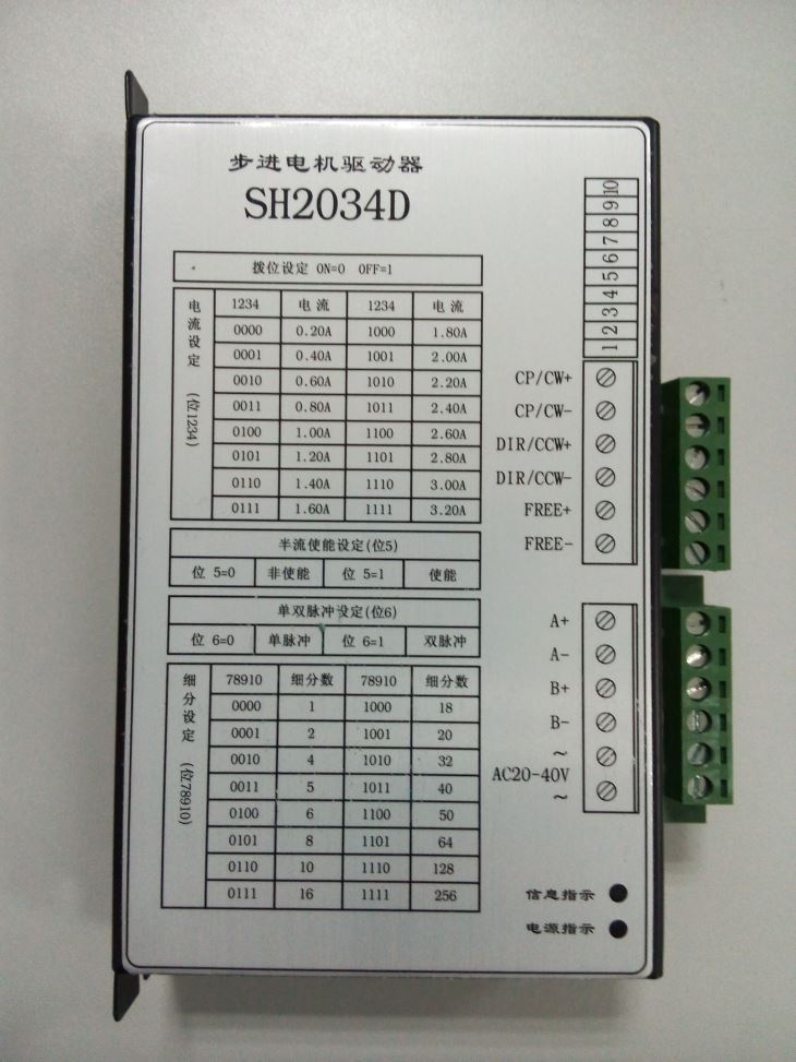
SH2034D
Stepping Motor Driver
I?Summarize
Based on the original stepping motor driver, we developed the 2034D type stepping motor driver. This driver owns many advantages such as lower noise, higher efficiency, lower temperature rise, convenient settings, nicer running characteristic and so on.
II?The using and instruction of the motor driver

Power supply:
Single external power supply:AC 20-40V 3A or DC 20-50V 3A?
Warning: The value of the power supply shouldn’t be over this range.
Wiring diagrams of motors:
For two-phase four-wire motor:
Phase | A+ | A- | NC | B+ | B- |
Wire | Red | Green | White Black | Yellow | Blue |
For four-phase six-wire motor:
Phase | A+ | A- | B+ | B- |
Wire | Red | Green | Yellow | Blue |
For four-phase eight-wire motor, there are two modes:
i. Parallel-wound
Phase | A+ | A- | B+ | B- |
Wire | Red Blue | Yellow Black | White Brown | Green Orange |
ii. Series-wound
Phase | A+ | A- | Nc1 | B+ | B- | Nc2 |
Wire | Red | Black | Yellow Blue | White | Green | Brown Orange |
Warning:Motor’s wires mustn’t be connected wrongly, Otherwise, the driver will be mangled.
Input signals
The inner interface circuits of the SH2034D are segregated by optically coupled isolators.
There are three connecting mode between the controller and the driver.
i. Differential ii. Common-anode


iii. Common-cathode

Signal Amplitude | R |
5V | --- |
12V | 680O |
24V | 1.8KO |
DIR:Input port of the direction signal. High/low level controls the CW/CCW of motor. The changing edge of the signal must be at least 2.5us later or earlier than the falling edge of CP;
FREE: Free signal (active low). when this input end is low level,there will be no holding torque of the motor.
CP: Pulse signal input. active by the falling edge,the highest response frequency can be 200kHz,low level pulse width should be not less than 2.5us?
Warning:Input signal must have enough current, (Currently, TTL, COMS signal are not drive firsthand). Otherwise, System can not run normally.
* phase current and subdivision number setting:
Shift switch is adopted to set phase current and subdivision number in SH2034D driver. There-into, Switch 5 is half phase-current (ON means full current, OFF means half), switch 6 is the setting of single or double pulse (ON show single pulse CP,DIR; OFF show double pulse CW,CCW). See Table2,Table3.After the subdivision of driver is set, the step angle in motor is equal to whole step angle divided by subdivision number. For example:if subdivision number is set to 18 and the motor is 2-phase,its subdivision step angle is 1.8°/18=0.1°?
Warning:shift switch ON=0,OFF=1.
Phase current(bit 1 2 3 4) | |||
1 2 3 4 | Value | 1 2 3 4 | Value |
0 0 0 0 | 0.20A | 1 0 0 0 | 1.80A |
0 0 0 1 | 0.40A | 1 0 0 1 | 2.00A |
0 0 1 0 | 0.60A | 1 0 1 0 | 2.20A |
0 0 1 1 | 0.80A | 1 0 1 1 | 2.40A |
0 1 0 0 | 1.00A | 1 1 0 0 | 2.60A |
0 1 0 1 | 1.20A | 1 1 0 1 | 2.80A |
0 1 1 0 | 1.40A | 1 1 1 0 | 3.00A |
0 1 1 1 | 1.60A | 1 1 1 1 | 3.20A |
subdivision(bit 7 8 9 10) | |||
7 8 9 10 | Number | 7 8 9 10 | Number |
0 0 0 0 | 1 | 1 0 0 0 | 18 |
0 0 0 1 | 2 | 1 0 0 1 | 20 |
0 0 1 0 | 4 | 1 0 1 0 | 32 |
0 0 1 1 | 5 | 1 0 1 1 | 40 |
0 1 0 0 | 6 | 1 1 0 0 | 50 |
0 1 0 1 | 8 | 1 1 0 1 | 64 |
0 1 1 0 | 10 | 1 1 1 0 | 128 |
0 1 1 1 | 16 | 1 1 1 1 | 256 |
III?Installation Dimension:
Disperse heat by compelling structure is adopted, so when installing, please keep enough space to elimination of heat when the driver installed (unit: mm)

IV. Signal indication
Phenomenon | Case | Solutions |
The signal light twinkles red (over current) | i. The motor wires are shortcut. | i. Examine the motor wires. |
The signal light twinkles red and orange. (overvoltage) | The power supply is over the range. | Turn down the power supply. |
The signal light be red. (under the lowest voltage) | The supply is too low. | Turn up the power supply. |
The signal light twinkles red and orange. | i. The temperature of the driver is too high. | i. Enlarge the proportion of radiator. |
The power light is red | The fuse is broken. | Change the fuse in the same type. |
-
DCH20403 50 Pieces / (Min. Order)
-
Stepper Motor With Encoder Feedback 15 Pieces / (Min. Order)
-
DCYJ-208 50 Pieces / (Min. Order)
-
DCH20403 50 Pieces / (Min. Order)
-
130ST-M15025 50 Pieces / (Min. Order)

-
130ST-M15015 50 Pieces / (Min. Order)
-
80ST-M03230 50 Pieces / (Min. Order)

-
80ST-M02430 50 Pieces / (Min. Order)

-
80ST-M01630 50 Pieces / (Min. Order)
-
60ST-M01930 50 Pieces / (Min. Order)
-
110S5P261-3010A 50 Pieces / (Min. Order)
-
110SH3P243-5203A 50 Pieces / (Min. Order)

-
110SH3P202-4803A 50 Pieces / (Min. Order)

-
110SH3P161-4203A 50 Pieces / (Min. Order)
-
110SH3P128-4203A 50 Pieces / (Min. Order)

-
86SH3P130-5803A 50 Pieces / (Min. Order)

-
86SH3P130-22503A 50 Pieces / (Min. Order)
-
86SH3P101-5803A 50 Pieces / (Min. Order)

-
86SH3P101-2003A 50 Pieces / (Min. Order)

-
130S281-6004A 50 Pieces / (Min. Order)
 Favorites

-
Stepper Motor With Encoder Feedback
15 Pieces / (Min. Order)
-
DCYJ-208
50 Pieces / (Min. Order)
-
DCH20403
50 Pieces / (Min. Order)
-
130ST-M15025
50 Pieces / (Min. Order)
-
130ST-M15015
50 Pieces / (Min. Order)
-
80ST-M03230
50 Pieces / (Min. Order)
-
80ST-M02430
50 Pieces / (Min. Order)
-
80ST-M01630
50 Pieces / (Min. Order)
-
60ST-M01930
50 Pieces / (Min. Order)
-
110S5P261-3010A
50 Pieces / (Min. Order)
-
110SH3P243-5203A
50 Pieces / (Min. Order)
-
110SH3P202-4803A
50 Pieces / (Min. Order)
-
110SH3P161-4203A
50 Pieces / (Min. Order)
-
110SH3P128-4203A
50 Pieces / (Min. Order)
-
86SH3P130-5803A
50 Pieces / (Min. Order)
-
86SH3P130-22503A
50 Pieces / (Min. Order)
-
86SH3P101-5803A
50 Pieces / (Min. Order)
-
86SH3P101-2003A
50 Pieces / (Min. Order)
-
130S281-6004A
50 Pieces / (Min. Order)